Prop Tarantula - Further Development : Legs

Prop Tarantula Preposed

Further Development

Legs

Issues

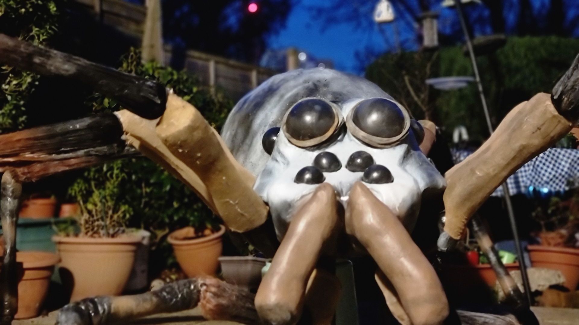
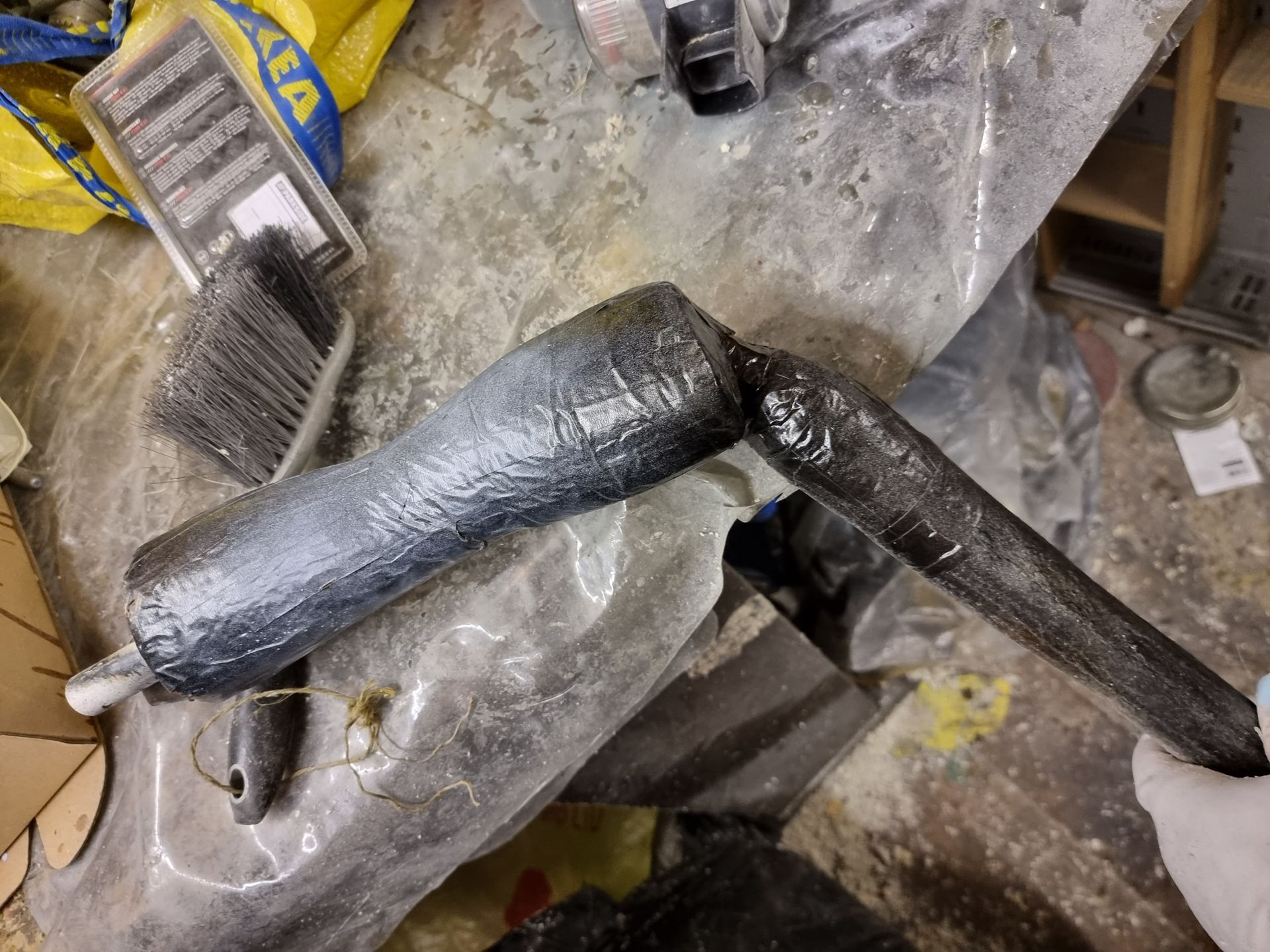
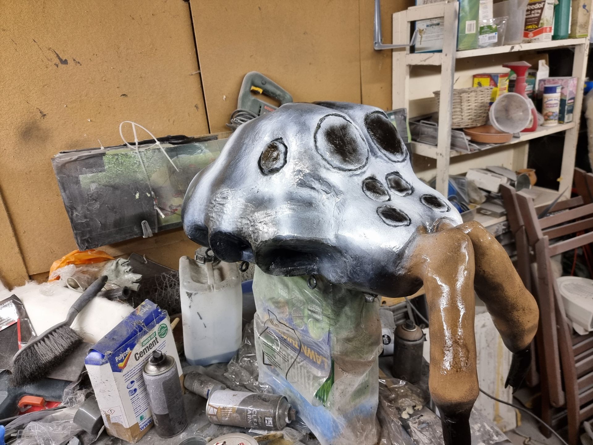
Clearly one of the biggest problems are the legs. They are far too weak, especially for the added spider weight

These were restarted several times at considerable cost and time. They are still not up to the task following the videos instructions to make the joints with hair curlers duct tape and thick garden wire.

Yes, they do form flexible joints but the problems include that they bend in all directions and off centre out of line with the legs. The leg segments appear in the wrong place in terms of length. The second from body end should be closest to the body. The legs should hold up the spider which has no considerably more weight with the glass fibre shell and my connector components.

The segments don’t appear to be in the best order and lengths to form the best structured arc

• Joints too weak and thus too loose to hold any weight.

• The joints are too wonky and are out of alignment.

• After the first joint on a leg which could be a ball multi directional joint the others need to stay inline.

• The legs are too thin in terms of the pipe diameter. Changes to these would require new connector component designs or some or of adapter component.

• The lengths appear to be incorrect lengths and order to form structurally strong high arcs.

• The extra effort to make the paint stick is not economical and prone to making a mess.

Proposed New Leg Design

JOINTS

Firstly, the joints need to be replaced by totally scrapping the bending wire system. 

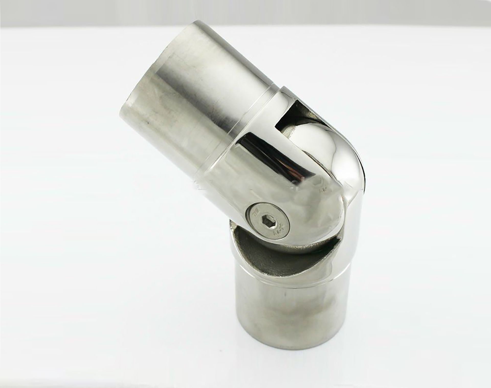
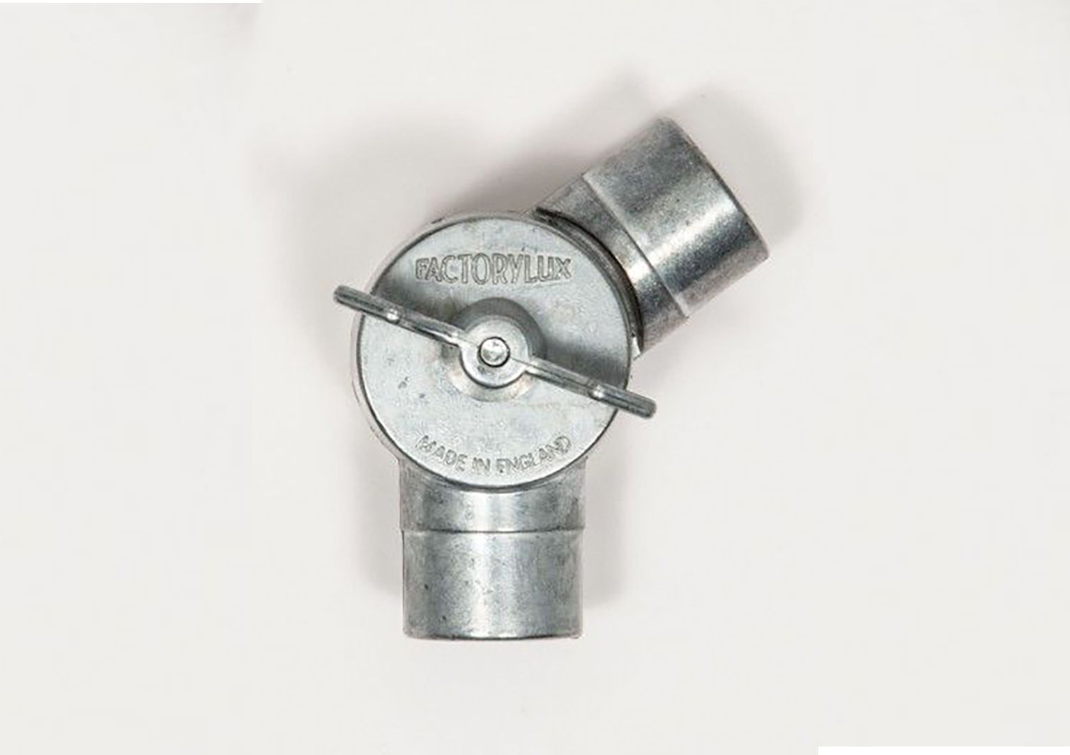
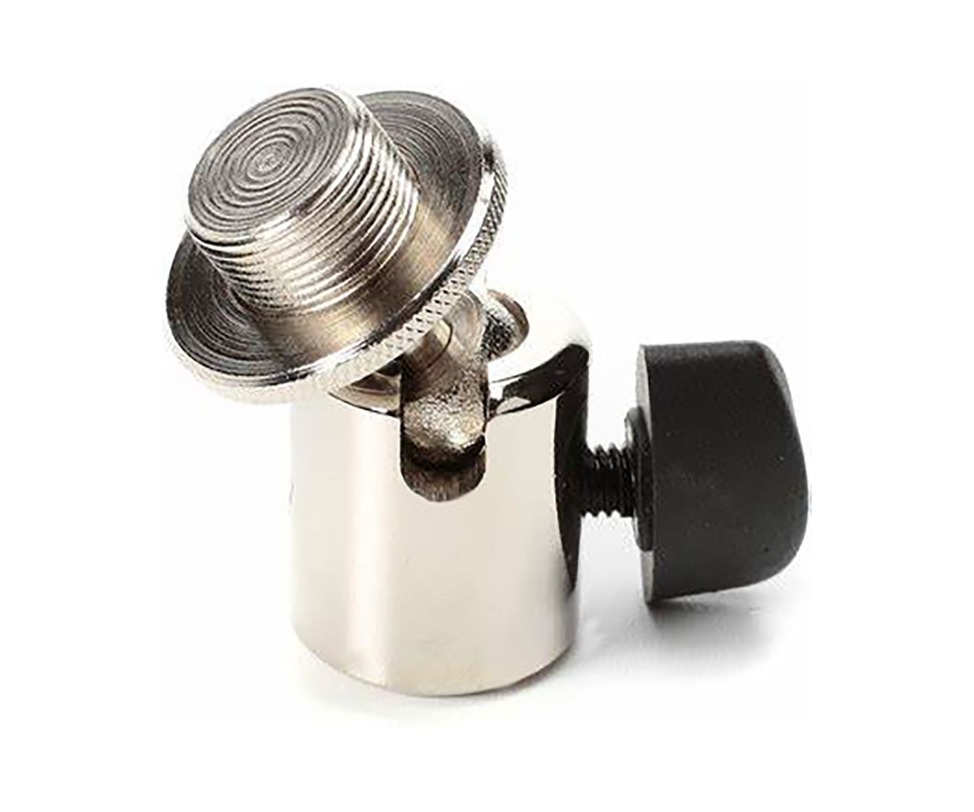
What are needed are lockable joints but without bulky appendages that could detract from an organic look. These would enable posing or possible puppet animation but also to solidly lock the legs into shape to help hold the weight.

The first joints with could form the high point of the leg arcs could be a ball joint, but the rest need to be single plane hinge joint to prevent side buckling, twisting and collapse.

It may be necessarily making all the joints single plane hinge points.

These joints need to be able to fit the round plastic pipes which would form the legs and lock in place not twist. Possibly by bolting.

LEG THICKNESS

The legs are clearly too thin to support the spider sufficiently and also, they look weak for the head and body. Thicker pipes not only will have more strength and stiffness, they would have a wider footprint base which would make the feet ends of the legs more stable on the floors and enable more options for adding a grippy material for hard surfaces on the ends and a system such as removable spike option for soft ground.

In addition to the thicker pipes opting for thicker pipe lagging would hold to give the legs more shape and definition

INCORRECT LEG LENGTH, ARC SHAPE AND ORDER

At present with a medium and then long length segment the legs are pushed to form a flatter shape that spreads away from the head, more of a flatter curve and this shape lacks structural strength so the spider head and body just collapse and cannot support weight.


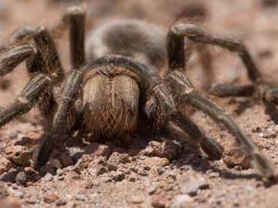
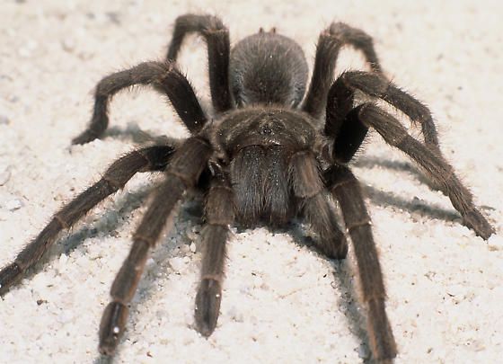
 The current shape of the legs does not seem to work and does not match up with how real spider legs tend to pose.

Starting with the body the legs should first point up at an acute angle, then down sharply with similar length with the next leg statement, then 2 to 3 short lengths that can curve. This should in effect form something like an upside-down V triangle shape.


RESHAPING CONNECTOR COMPONENTS

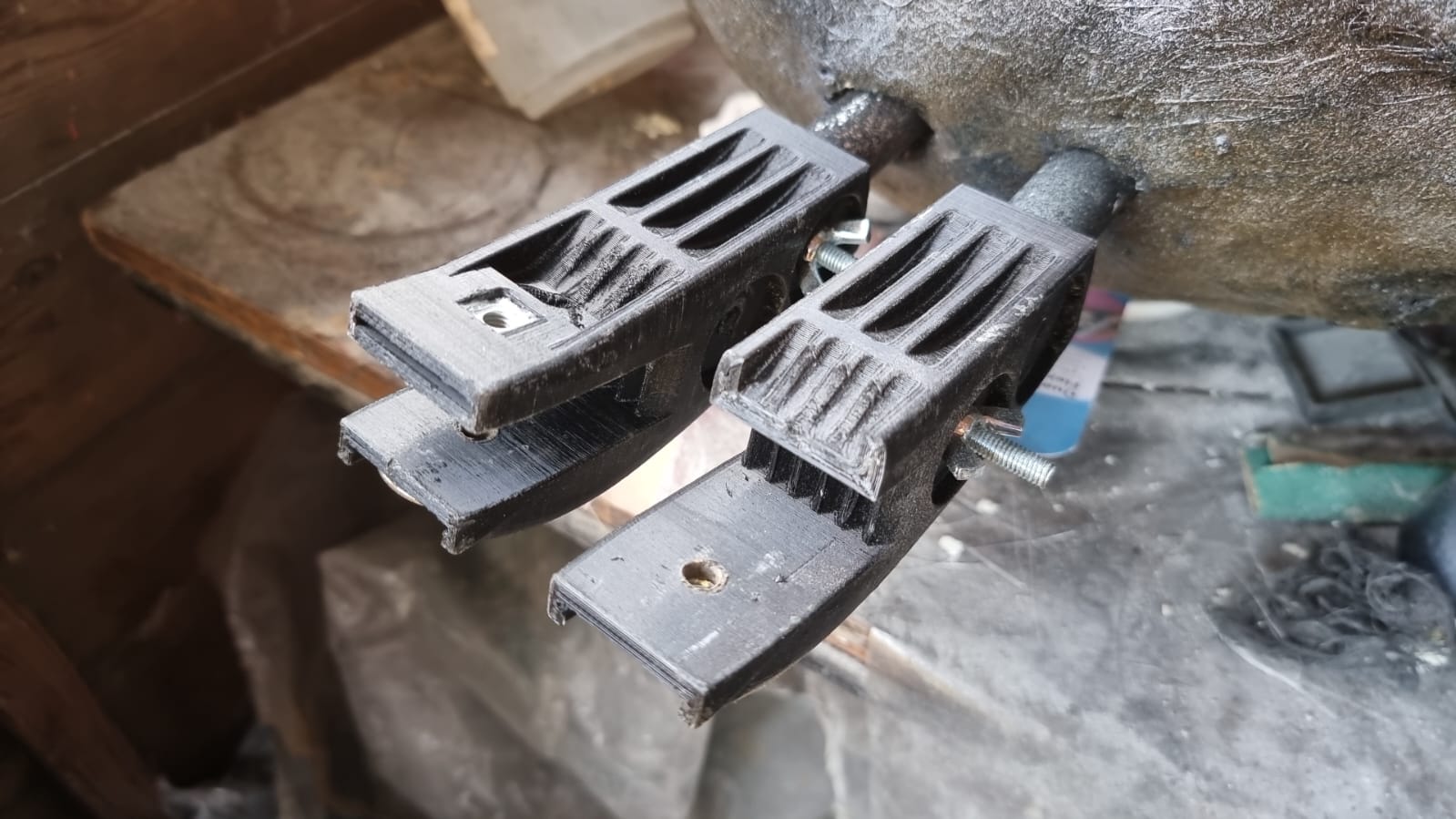
In order to have the legs starting at a more vertical acute angle, the connector components will need to extend away from the body to cleat it then the connectors need to bend up at an angle much closer to 90degrees up maybe 80. This can be done with another CAD iteration.


This time it could be redesigned to be able to be cast and moulded from the first 3D print rather than multiple very time consuming and costly 3D prints


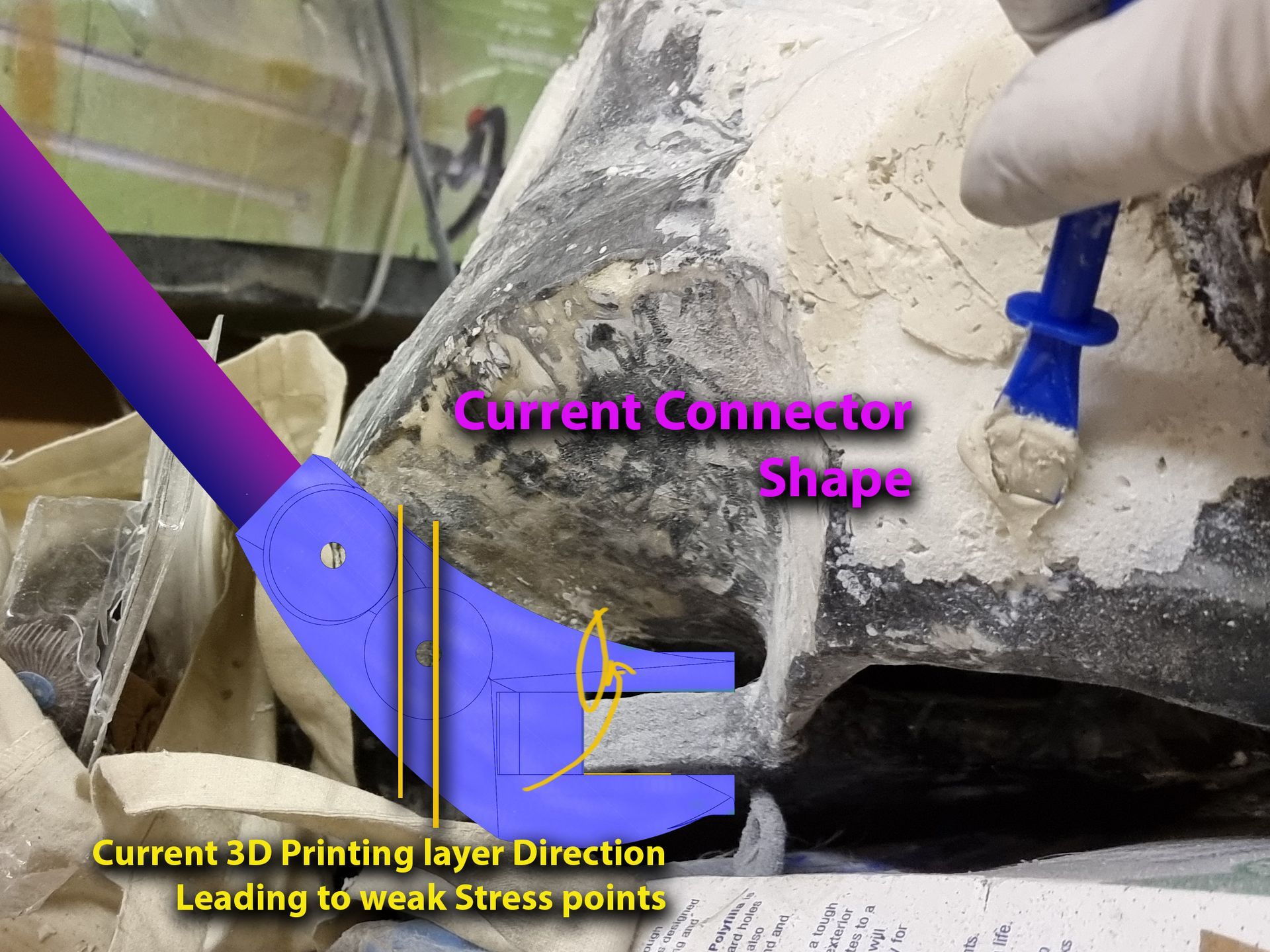
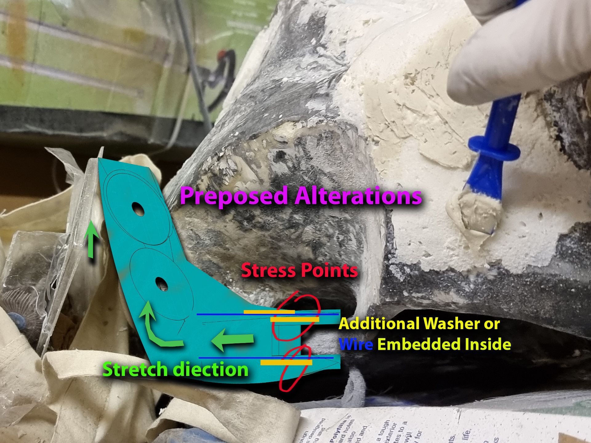
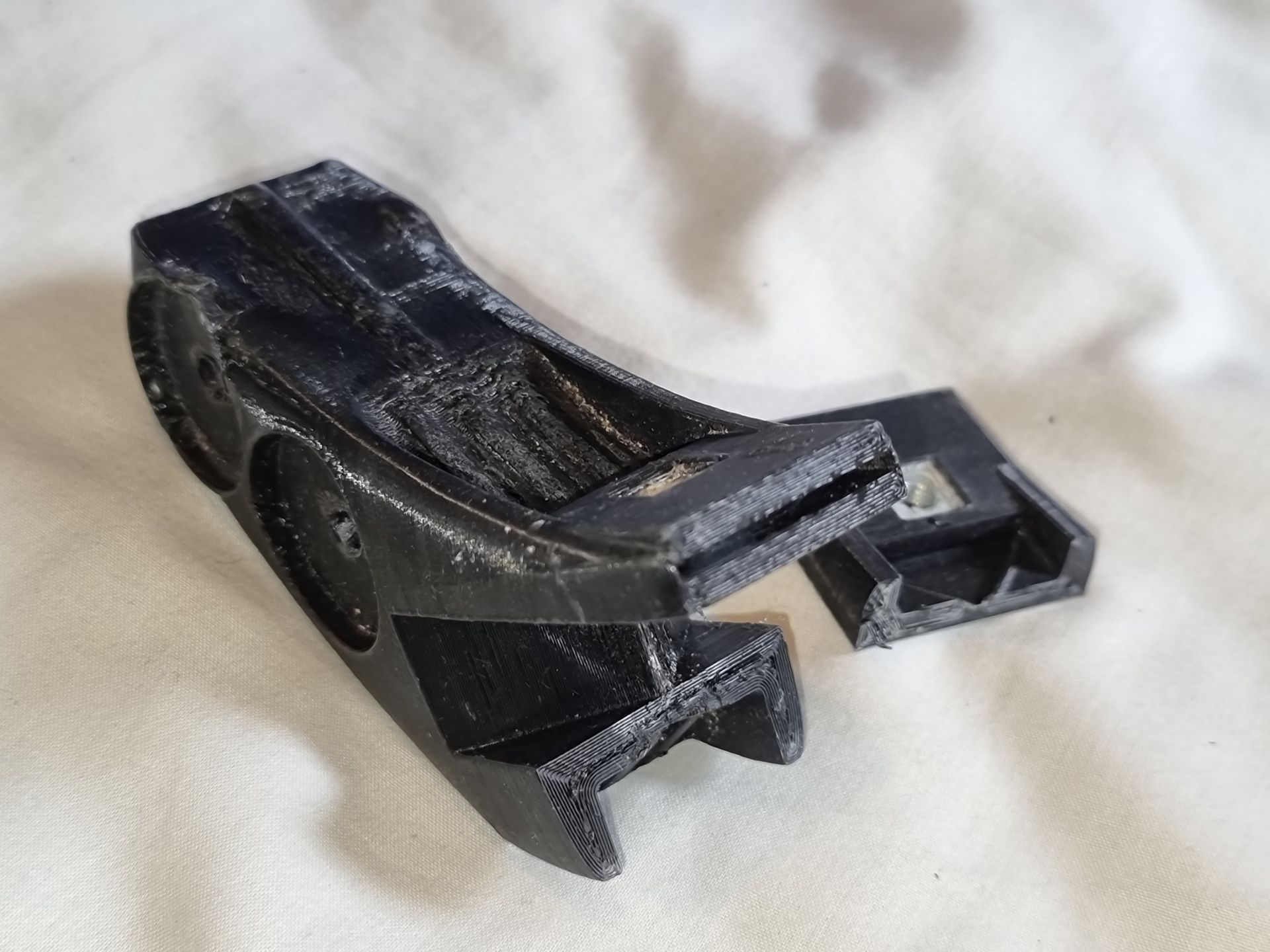
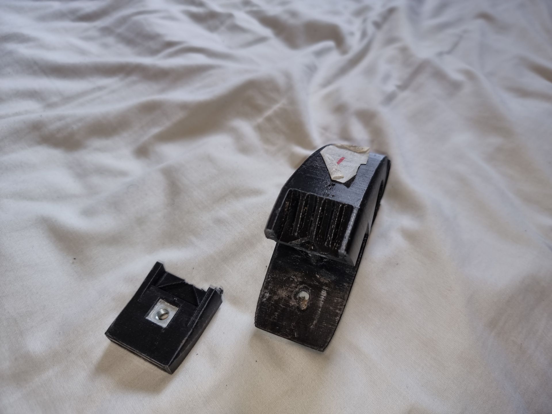
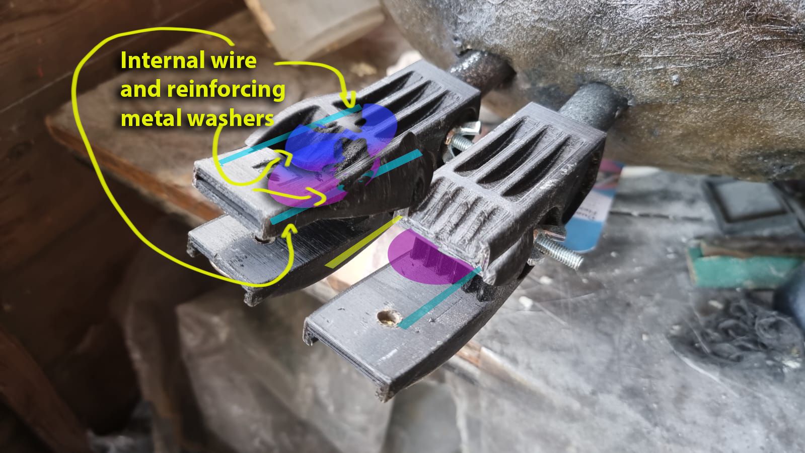
When photographing the latest working spider and trying to handle it, one leg and one of the bodies holding connectors snapped at the point just inside the washer where it camps onto the board. This indicates a weak stress point subject to sheer forced due to the weight just beyond where it connects to the board. Much like standing on a stick and pulling it up. This would be substantially increased if at first the connector is stretched away from  the head board giving the forces much more leverage.


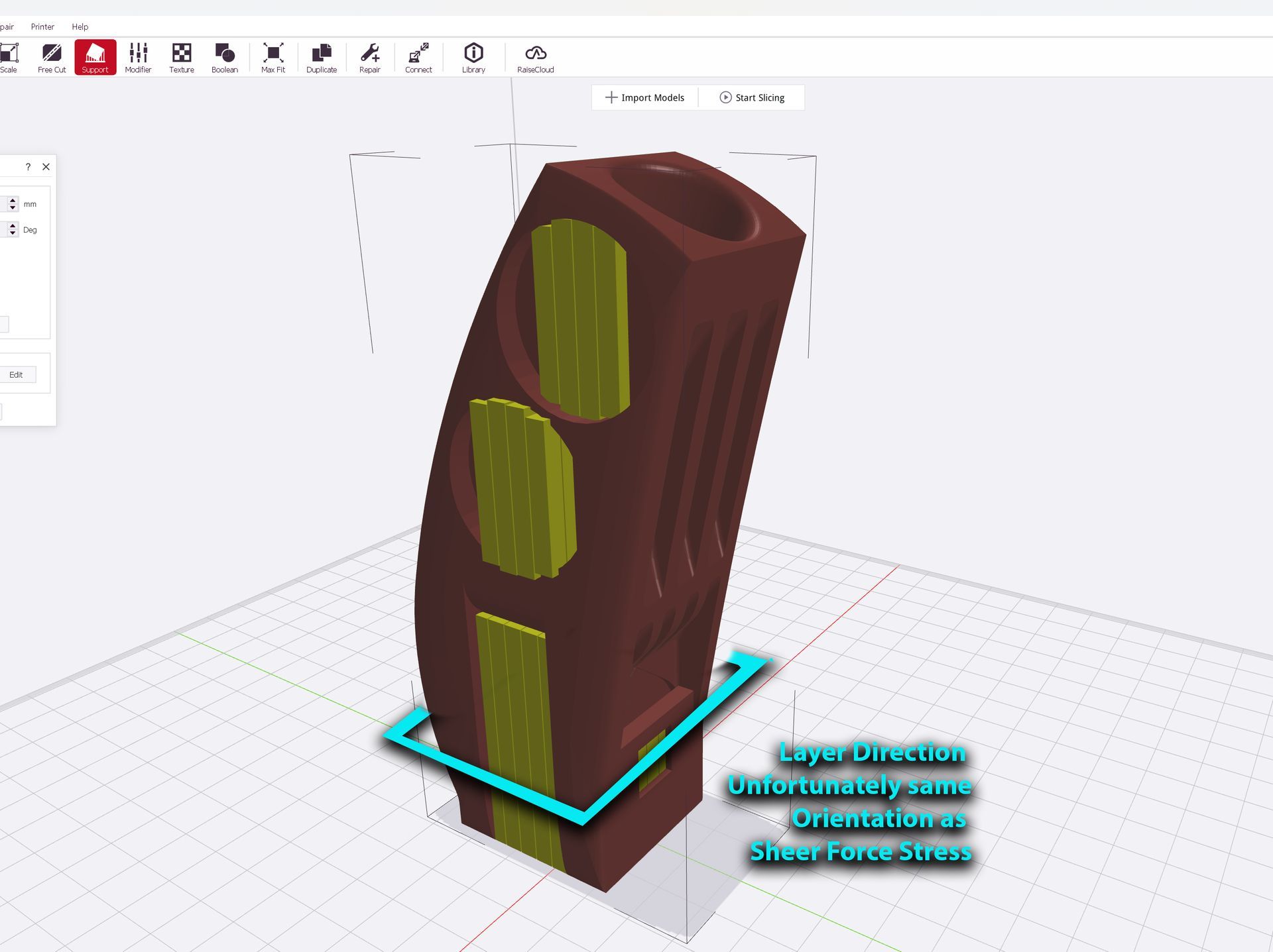
This is substantially increased in terms of how the 3D printing is achieved in layers. To minimise the need for supports and deformations as seen below the print was set up to print vertically. Whilst this works well for the 3d Printing the orientation for maximum strength needs to be lengt wise not width wise.


Think Lego as a thin tower. It the bricks used are small or loops one on top of the other like a chimney this worked well under pressure but if the force comes in sideways the tower is easily snapped as in lines with the layer breaks.


In like bricks are used to make the tower horizontally this is far more solid


The next iteration will need to structurally strengthen this point, much more it is is where the connector will be extended outwards.


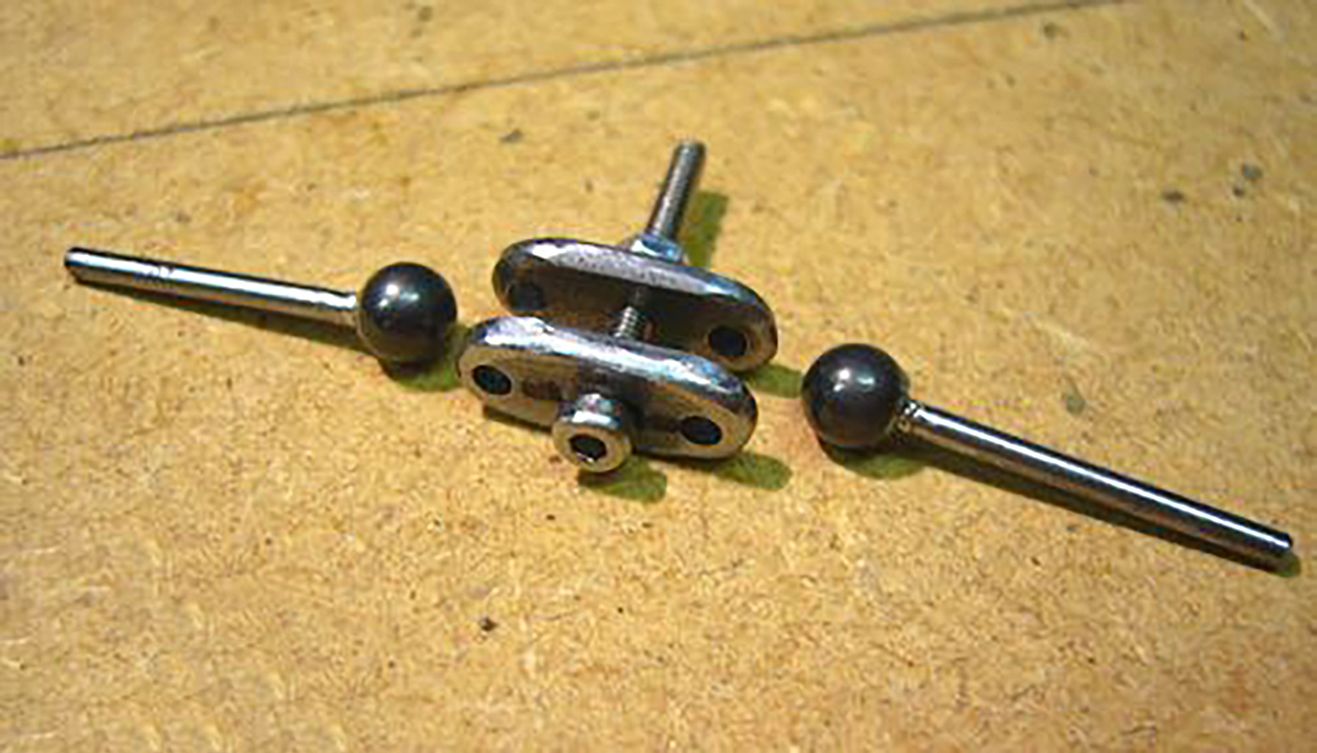
This could be strengthen but sealing into the 4mm wire rods much like in reinforced concrete and over over lapping metal washers embedded over weak points. However this would add to the weight. Also a thicker unit is not necessarily stronger as 3D prints tend to be hollow. The strength is in the walls so one with 3mm wires in the right orientation should be stronger as would any that have been casts ideally with metal rods inside.

On way may be to double the depth of the washer slot so 2 can be added or a way to have them over lapping.


Then have the banana like curve to the part that holds the leg, be curved more inwards at a more near vertical angle.


LEG SURFACE

While there have been several improvements to make the leg surface more adhesive to paint such as using a wire brush to shred the shiny pipe lagging skin surface, coating the duct tape in frog masking tape, then spray gluing and coating the tape on the legs with the dust and small fragments of insulation foam.


Ideally this needs to minimise the steps, material and expense if switching to mechanical hinge or ball joints so less need for shiny non-stick tape.


Also the pipe lagging could be completely replaced with Plastazote foam or  moulded and gun foam cast ings


NON-PAINTED FOLDS AND TEARS ON JOINTS

As mentioned, a problem with the brightly coloured frog tape over the joints. As the joint bends causing stretches and compression if forms fold that either tear exposing the plastic tape underneath or compress folds so the spray paint cannot get to that spot. The tape then created highlighted spots as the leg joint flexes which ruins the effect. 


A A stuck and semi sewn on stretchy textured material could help here, possibly nylon tights or Lycra may help here going forward., as a skin over ball and socket and lockable hinge joints.

Spider
Title & Intro
Page

This was a double bed size prop Tarantula, originally intended as a cool Halloween front of house prop as well as portfolio piece to discuss project development.

Finished project page.


View More

Spider Project

Development  


Projects Accounting Costs
Spider  Initial Research & PPP Testing

To start the project was looking into existing props and Halloween tableaus and how such a project could be done. 
Initial Proving Principle Prototyping & scale modelling.


View More

Spider
Development
 Head

The main central part is the head to which all other parts are connected and would be the section to connect stands and load supports.

This involved the most substantial development  and most restarts.
View More
Spider
Development
Body

This had a similar basic structure to the head but a lot simpler. It does have its own issues and problems.

This had to be re-opened for upgrades to strengthen  the connections to the head.
View More
Spider
Development
Legs

The legs required repeated and costly redesign and rebuilding building to try and build enough strength into them to be able to support the weight of the spider, as well as look realistic and bond the paint to them.

View More
Spider  Development
Leg Connector

The system to connect the legs needed substantial improvement and iterations developing these connection components through CAD and rapid prototypng. 


View More

Further Development
Head

Further planned developments & problem solving for the head.

The next staage here would be fur.


View More
Further Development
Body

Further planned developments & problem solving for the body.

This will need to be split into sections for storage that can be easily reassembled.

View More
Further Development
Legs & Connectors

Further planned developments & problem solving for the legs, strengthening them to support the weight of the  spider.


View More
Further Development
Skin and Fur

Plans to further develop the prop Tarantula and current unsolved problemsand issues


View More
Share by: